🚚 Free Worldwide Shipping on All Orders!Shop Now
$0.47
Original: $1.56
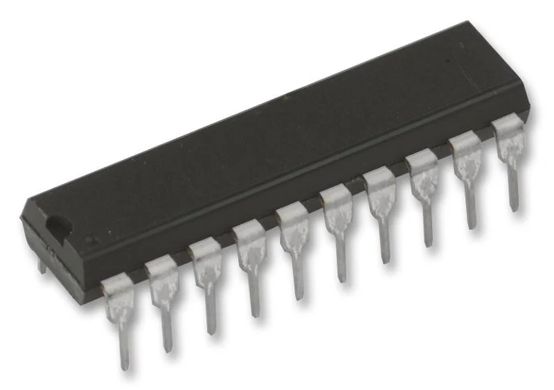
-70%Texas Instruments SN74HCT273N SN74HCT273N Flip-Flop With Clear Non Inverted Positive Edge 74HCT273 D 12 ns 37 MHz 4 mA DIP—
$1.56
$0.47The Story
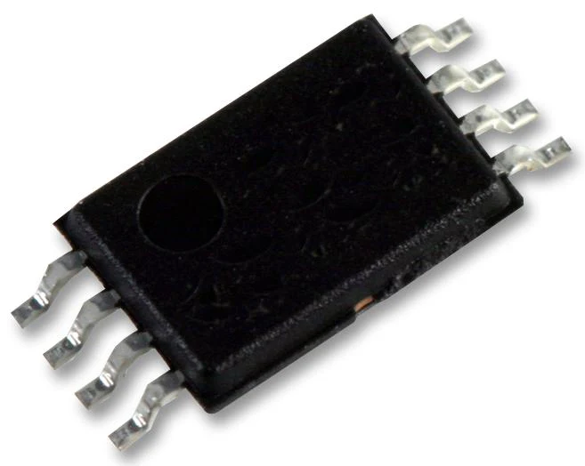
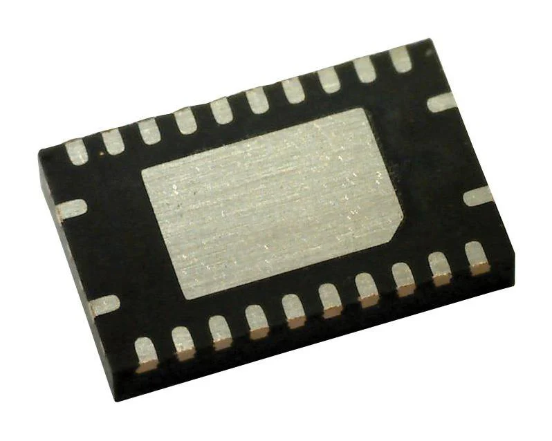
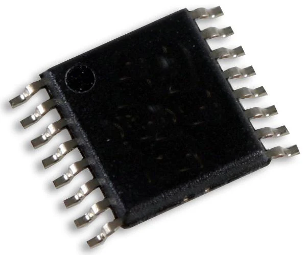
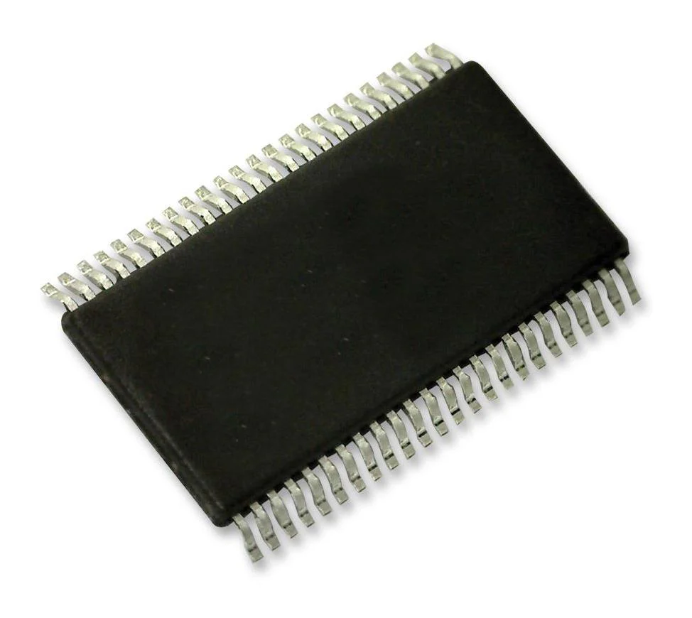
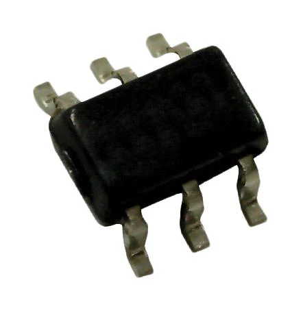
The SN74HCT273N is an octal positive-edge-triggered D-type Flip-flop with clear and common enable input. The HCT273 devices are similar to the HCT377 devices, but feature a common clear enable (CLR\) input instead of a latched clock. Information at the data (D) inputs meeting the setup time requirements is transferred to the Q outputs on the positive-going edge of the clock (CLK) pulse. Clock triggering occurs at a particular voltage level and is not directly related to the positive-going pulse. When CLK is at either the high or low level, the D input has no effect at the output. The circuits are designed to prevent false clocking by transitions at (CLR\).
- Outputs can drive up to 10 LSTTL loads
- Inputs are TTL-voltage compatible
- Typical tpd = 12ns
- 80µA Maximum low power consumption
- ±4mA Output drive at 5V
- 1µA Maximum low input current
Industrial
Other details
| Brand | TEXAS INSTRUMENTS |
| Part Number | SN74HCT273N |
| Quantity | Each |
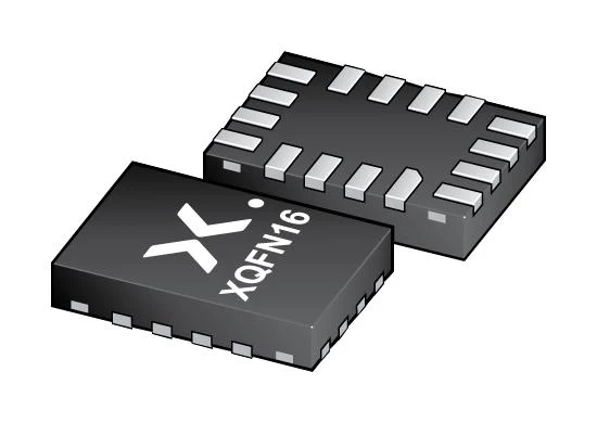
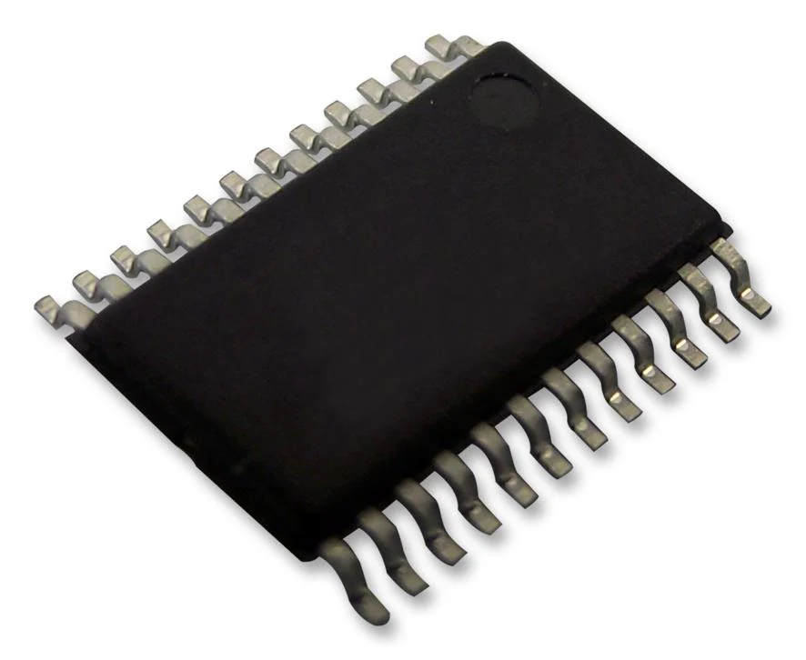
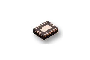
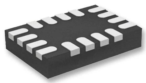
All product and company names are trademarks™ or registered® trademarks of their respective holders. Use of them does not imply any affiliation with or endorsement by them. Image is for illustrative purposes only. Please refer to product description.
Description
The SN74HCT273N is an octal positive-edge-triggered D-type Flip-flop with clear and common enable input. The HCT273 devices are similar to the HCT377 devices, but feature a common clear enable (CLR\) input instead of a latched clock. Information at the data (D) inputs meeting the setup time requirements is transferred to the Q outputs on the positive-going edge of the clock (CLK) pulse. Clock triggering occurs at a particular voltage level and is not directly related to the positive-going pulse. When CLK is at either the high or low level, the D input has no effect at the output. The circuits are designed to prevent false clocking by transitions at (CLR\).
- Outputs can drive up to 10 LSTTL loads
- Inputs are TTL-voltage compatible
- Typical tpd = 12ns
- 80µA Maximum low power consumption
- ±4mA Output drive at 5V
- 1µA Maximum low input current
Industrial
Other details
| Brand | TEXAS INSTRUMENTS |
| Part Number | SN74HCT273N |
| Quantity | Each |
All product and company names are trademarks™ or registered® trademarks of their respective holders. Use of them does not imply any affiliation with or endorsement by them. Image is for illustrative purposes only. Please refer to product description.